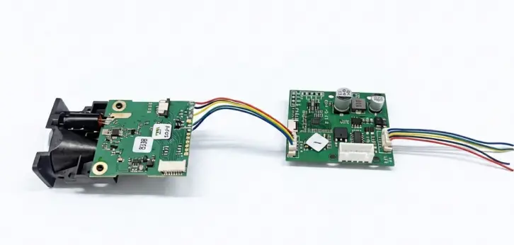
Choosing the right laser distance sensor interface is an important part of integrating a sensor into an industrial system. The interface affects how the sensor communicates with a PLC, industrial PC, microcontroller, or other controller, as well as how multiple sensors can share a network and how reliably the system operates in electrically noisy environments.
Common laser distance sensor interfaces and communication options include RS485, Modbus RTU, CAN, RS232, and UART/TTL. However, these terms do not all describe the same layer of communication. RS485 and UART, for example, describe electrical interfaces, while Modbus defines a communication protocol that commonly runs over RS485.
This guide explains the main laser distance sensor interface options and shows how to choose between RS485, Modbus RTU, CAN, and UART/TTL for industrial automation, OEM equipment, mobile platforms, and embedded systems.
Laser Distance Sensor Interface: The 30-Second Summary
If you only need the basic decision, use these rules:
| Interface or protocol | What it defines | Typical application |
|---|---|---|
| RS485 | Differential electrical interface | Industrial sensors, long cable runs, noisy environments |
| Modbus RTU | Communication protocol, commonly over RS485 | PLC, HMI, SCADA, and multi-sensor systems |
| CAN | Bus communication system with physical and data-link mechanisms | AGVs, AMRs, vehicles, mobile equipment |
| UART/TTL | Short-range serial electrical interface | Embedded systems and microcontrollers |
| RS232 | Point-to-point serial electrical interface | Short industrial connections and legacy equipment |
The most important distinction is:
RS485 defines how electrical signals are transmitted. Modbus defines how data is organized and exchanged. CAN uses its own bus communication mechanism and is commonly combined with higher-layer protocols.
For example, a laser distance sensor can be configured as:
RS485 + Modbus RTU
rather than choosing “RS485 or Modbus.”
This distinction becomes important when selecting a sensor for a PLC, industrial controller, or OEM system.
RS485 for Laser Distance Sensors
RS485 is one of the most widely used electrical interfaces for industrial sensors.
It uses differential signaling to transmit data, which provides good resistance to common-mode electrical interference. This makes RS485 suitable for factory environments containing motors, variable-frequency drives, relays, welding equipment, and other sources of electrical noise.
For laser distance sensors, RS485 is commonly used when the sensor needs to communicate with a PLC, industrial PC, embedded controller, or another device over a relatively long cable.
What makes RS485 suitable for industrial sensors?
Typical characteristics include:
- Differential signaling
- Multi-device bus capability
- Good noise immunity when correctly installed
- Long-distance communication at appropriate baud rates
- Compatibility with multiple communication protocols
- Relatively low hardware cost
- Wide adoption in industrial automation
The actual communication distance depends on baud rate, cable characteristics, transceiver design, network topology, and environmental conditions.
The frequently cited 1200 m figure should therefore be treated as a practical reference for suitable RS485 installations rather than a guaranteed distance under every operating condition.
When should you choose RS485?
RS485 is a good option when:
- The sensor is several meters or more from the controller.
- Multiple sensors need to share a communication bus.
- The system operates in an electrically noisy environment.
- The controller supports serial communication.
- You want to use Modbus RTU or a custom serial protocol.
- Cost and simplicity are important.
RS485 bus topology
A typical RS485 network uses a linear bus or daisy-chain topology.
For example:
PLC
 │
 ├── Sensor 1
 │
 ├── Sensor 2
 │
 ├── Sensor 3
 │
 └── Sensor 4
The main communication cable should generally run from one device to the next. Long cable stubs and star-shaped wiring can create signal reflections and communication problems, particularly at higher baud rates.
For a properly designed bus, termination resistors are normally installed at the two physical ends of the main cable. A common termination value is 120 Ω, depending on the cable and network design.
Common RS485 integration problems
A sensor having an RS485 connector does not automatically mean that it will work reliably after simply connecting two wires.
Important installation factors include:
- Bus topology
- Cable type
- Cable length
- Baud rate
- Device addressing
- Termination
- Shielding and grounding
- Cable routing
- Electromagnetic interference
For industrial laser distance sensors, communication reliability depends on the complete RS485 network rather than the connector alone.
Modbus RTU for Laser Distance Sensors
Modbus is different from RS485.
RS485 is an electrical interface, while Modbus is a communication protocol.
Modbus was originally developed by Modicon and has become one of the most widely used communication protocols in industrial automation.
For laser distance sensors, one of the most common configurations is:
Modbus RTU over RS485
This combination is popular because RS485 provides the physical communication layer while Modbus RTU provides a standardized structure for exchanging measurement and configuration data.
How Modbus RTU works
A typical Modbus RTU system contains a controller and one or more connected devices.
A simplified Modbus RTU message can be represented as:
[Device Address] [Function Code] [Data] [CRC]The controller can request measurement data from a sensor or write configuration parameters to it.
Common Modbus function codes include:
0x03— Read Holding Registers0x04— Read Input Registers0x06— Write Single Register0x10— Write Multiple Registers
The actual register addresses and data formats depend on the sensor manufacturer.
For example, a laser distance sensor may provide registers for:
- Measured distance
- Signal strength
- Measurement status
- Device address
- Measurement mode
- Output rate
- Configuration parameters
The manufacturer’s communication manual or register map is required to interpret these values correctly.
When should you choose Modbus RTU?
Modbus RTU is particularly suitable when:
- Your PLC already supports Modbus.
- You are connecting several sensors.
- Your HMI or SCADA system uses Modbus.
- You need standardized register-based communication.
- You want to configure sensors remotely.
- You need straightforward integration with industrial automation equipment.
RS485 vs. Modbus: What’s the Difference?
This is one of the most common points of confusion when selecting a laser distance sensor.
Consider two sensors:
Sensor A
RS485
+
Manufacturer-specific protocol
Sensor B
RS485
+
Modbus RTU
Both sensors use RS485 electrically.
However, the controller communicates with them differently.
Sensor A requires the controller to follow the manufacturer’s custom command structure.
Sensor B uses Modbus RTU commands and the manufacturer’s register map.
Therefore:
RS485 tells you how the electrical signals are transmitted. Modbus tells you how the information is organized and exchanged.
When specifying a sensor, it is therefore better to request:
RS485 with Modbus RTU
rather than simply:
Modbus
CAN Interface for Laser Distance Sensors
CAN, or Controller Area Network, is another important communication option for laser distance sensors.
Originally developed for automotive systems, CAN is now widely used in:
- AGVs
- AMRs
- Mobile robots
- Vehicles
- Construction equipment
- Agricultural machinery
- Industrial machinery
- Embedded control systems
CAN is particularly useful in distributed systems where several devices or controllers need to communicate over the same network.
What makes CAN different?
CAN provides mechanisms for:
- Message arbitration
- Error detection
- Acknowledgement
- Fault handling
- Multi-master communication
Unlike a traditional master-controlled Modbus RTU network, CAN allows multiple nodes to attempt communication on the bus.
CAN arbitration determines which message gets access to the bus without requiring a central master to control every transmission.
This makes CAN particularly useful for distributed and mobile systems.
CAN communication speed and distance
Classical CAN supports communication rates up to 1 Mbps, although the practical maximum speed depends on bus length and network design.
As with RS485, longer cable lengths generally require lower communication speeds.
CAN networks typically use a linear bus topology with termination at the two physical ends of the network.
CAN and higher-layer protocols
CAN defines important parts of the communication mechanism, but application-level systems often use additional protocols.
Examples include:
- CANopen
- J1939
- DeviceNet
- Manufacturer-specific CAN protocols
Therefore, when evaluating a laser distance sensor with CAN, you should ask not only:
Does the sensor support CAN?
but also:
Which CAN protocol or message format does the sensor use?
This can make a significant difference during system integration.
When should you choose CAN?
CAN is particularly suitable when:
- The sensor is installed on an AGV or AMR.
- The sensor is part of a vehicle or mobile machine.
- Multiple controllers need to communicate.
- Multi-master communication is useful.
- The system requires robust error detection.
- Your existing control architecture already uses CANopen, J1939, or another CAN-based protocol.
UART/TTL Interface for Laser Distance Sensors
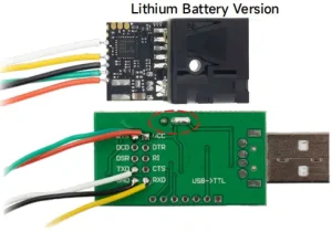
UART is another common communication option, particularly for embedded laser distance sensor modules.
UART itself is a serial communication method. TTL refers to the electrical signaling level commonly used by microcontrollers and embedded electronics.
A typical architecture may look like:
Laser Distance Sensor
        │
      UART
        │
Microcontroller
This is particularly suitable when the sensor is physically close to the controller.
When should you choose UART/TTL?
UART/TTL is often appropriate when:
- The sensor is located close to a microcontroller.
- Cable length is short.
- The electrical environment is relatively clean.
- You are designing an embedded product.
- You want a simple serial communication interface.
- The controller already has a UART port.
UART/TTL is generally not intended for the same long-distance industrial bus applications as RS485.
If the sensor must be installed tens or hundreds of meters away from the controller, RS485 or CAN may be more appropriate depending on the system architecture.
UART vs. RS485
The key difference is the electrical environment and communication distance.
| Characteristic | UART/TTL | RS485 |
|---|---|---|
| Typical use | Embedded electronics | Industrial equipment |
| Signaling | Single-ended | Differential |
| Multi-device bus | Not normally used directly | Yes |
| Noise resistance | Lower | Higher |
| Cable distance | Short | Much longer |
| Typical controller | Microcontroller | PLC/industrial controller |
| Industrial applications | Limited | Very common |
For an OEM laser distance sensor module installed inside a compact device, UART/TTL may be sufficient.
For a sensor installed on a production line several meters away from the controller, RS485 is often more appropriate.
RS232 for Laser Distance Sensors
RS232 is another serial interface that may appear on industrial laser distance sensors.
Unlike RS485, RS232 is normally designed for point-to-point communication rather than a multi-device bus.
A typical connection is:
Sensor ───────── ControllerRS232 can be useful when:
- Only one sensor needs to connect to the controller.
- The cable is relatively short.
- The controller already has an RS232 port.
- You are integrating with existing industrial equipment.
However, RS232 is generally less suitable than RS485 when multiple sensors need to share one communication bus.
Laser Distance Sensor Interface Comparison
The following table summarizes the main options.
| Characteristic | UART/TTL | RS232 | RS485 | Modbus RTU over RS485 | CAN |
|---|---|---|---|---|---|
| Main role | Serial interface | Serial interface | Differential interface | Communication protocol + RS485 | Bus communication system |
| Differential | No | No | Yes | Yes | Yes |
| Multi-device bus | No | Generally no | Yes | Yes | Yes |
| Multi-master | No | No | Not inherently | Typically no | Yes |
| Typical application | Embedded systems | Point-to-point equipment | Industrial sensors | PLC/HMI/SCADA | Mobile/distributed systems |
| Noise resistance | Lower | Moderate | High | High | High |
| Long cable capability | Limited | Limited | High | High | High at appropriate bit rates |
| PLC integration | Depends on PLC | Common in some equipment | Common | Very common | Depends on controller |
| Data protocol | UART-based/custom | Application-specific | Application-specific | Standardized | CAN frame + higher-layer protocol |
| Typical complexity | Low | Low | Moderate | Low to moderate | Moderate to high |
The most important point is that Modbus RTU should not be treated as a physical interface competing directly with RS485.
A more accurate comparison is:
UART/TTL vs. RS232 vs. RS485 vs. CAN for electrical/bus architecture, with Modbus RTU as a protocol commonly used on RS485.
How to Choose a Laser Distance Sensor Interface
The best laser distance sensor interface depends on the complete system architecture.
Instead of starting with the sensor connector, start with the controller and installation environment.
Choose UART/TTL when:
- The sensor is close to the microcontroller.
- The cable is short.
- The environment has limited electrical interference.
- You are developing an embedded product.
- You need a simple serial connection.
Choose RS232 when:
- You have a single sensor.
- The controller already supports RS232.
- The cable is relatively short.
- Point-to-point communication is sufficient.
Choose RS485 when:
- The sensor is installed several meters or more from the controller.
- The environment contains electrical noise.
- Multiple devices may share a bus.
- You need a robust industrial serial connection.
- You plan to use a custom serial protocol or Modbus RTU.
Choose Modbus RTU over RS485 when:
- The controller is a PLC, HMI, or industrial PC.
- Multiple laser sensors need to communicate with one controller.
- You need standardized register-based communication.
- Your automation system already uses Modbus.
- Remote sensor configuration is required.
Choose CAN when:
- The sensor is installed on an AGV, AMR, vehicle, or mobile machine.
- Multiple controllers or devices communicate on the same network.
- Multi-master communication is useful.
- Your existing architecture is CAN-based.
- Robust error detection and bus arbitration are important.
Practical Example: Four Laser Distance Sensors on a Gantry Crane
Consider a gantry crane with four laser distance sensors.
Each sensor measures the position of one corner of a load.
The system requirements are:
- 4 laser distance sensors
- Approximately 50 m of total cable distance
- Industrial PLC controller
- Welding-shop environment
- Multiple motors and electrical equipment
- Periodic measurement rather than extremely high-speed closed-loop control
A typical architecture could use Modbus RTU over RS485:
                    Industrial PLC
                         │
                       RS485
                         │
          ┌──────────────┼──────────────┐
          │              │              │
      Sensor 1       Sensor 2       Sensor 3       Sensor 4
      Address 01     Address 02     Address 03     Address 04
Each sensor receives a unique Modbus address.
The PLC polls the sensors and reads the required measurement registers.
Important engineering considerations include:
- Unique device addresses
- Appropriate baud rate
- Suitable twisted-pair communication cable
- Linear bus topology
- Correct termination
- Proper grounding and shielding
- Separation from high-power wiring where practical
- PLC polling cycle
- Sensor response time
The actual communication cycle should be calculated from the sensor’s response time, baud rate, message length, PLC scan cycle, and number of sensors.
Therefore, a statement such as “four sensors can always be read every 200 ms” should not be assumed without checking the actual sensor and PLC specifications.
Interface Is Not the Only Sensor Specification
Choosing a laser distance sensor interface is only one part of the sensor selection process.
A sensor with the correct communication interface may still be unsuitable if its measurement performance or mechanical design does not match the application.
Before selecting a sensor, also evaluate the following specifications.
1. Measurement range
Determine the actual minimum and maximum measurement distance.
For example:
- Short-range measurement
- 0–50 m industrial measurement
- 100 m+ outdoor measurement
- Long-range equipment positioning
- Kilometer-level measurement
Do not select a sensor based only on its maximum range. Target reflectivity, environmental conditions, and measurement accuracy can affect usable range.
2. Accuracy and repeatability
Accuracy and repeatability describe different aspects of measurement performance.
For positioning and inspection systems, both may need to be considered.
3. Response time and measurement frequency
Response time and measurement frequency should not automatically be treated as identical specifications.
A sensor may provide a high measurement frequency while having different effective response characteristics depending on measurement mode, filtering, target conditions, and signal processing.
For dynamic applications, evaluate the actual response-time requirement rather than looking only at the maximum frequency.
4. Communication interface and protocol
Always confirm both:
Physical interface
- UART/TTL
- RS232
- RS485
- CAN
- USB
and:
Communication protocol
- Modbus RTU
- ASCII
- CANopen
- J1939
- Proprietary protocol
This is particularly important for OEM projects.
5. Environmental protection
For outdoor and industrial applications, check the actual enclosure rating.
For example, an IP67-rated enclosure provides protection against dust and temporary immersion in water under the conditions defined by the IP rating.
The appropriate protection level depends on the installation environment.
6. Power supply
Check:
- Input voltage
- Current consumption
- Startup behavior
- Connector type
- Power wiring
- Communication wiring
7. Mechanical integration
OEM equipment may also require:
- Compact dimensions
- Mounting holes
- Specific optical window
- Custom connector
- Custom cable length
- Specific cable direction
- Customized enclosure
- IP-rated housing
For production equipment, these mechanical requirements can be just as important as the communication interface.
How to Specify a Laser Distance Sensor Interface
A request such as:
“I need a laser distance sensor with RS485.”
may not provide enough information for a manufacturer to select the appropriate configuration.
A more complete technical requirement might look like this:
Measurement range: 0.2–50 m
Accuracy: ±2 mm
Interface: RS485
Protocol: Modbus RTU
Supply voltage: 12–24 VDC
Measurement frequency: ≥50 Hz
Installation: Indoor industrial equipment
Quantity: 20 units
For OEM projects, it is also useful to provide:
- PLC or controller model
- Required communication protocol
- Number of sensors
- Cable length
- Required update rate
- Operating environment
- Connector requirements
- Housing requirements
- Required register map
- Required command structure
Providing these details at the beginning of the project can reduce compatibility issues during integration.
Custom Laser Distance Sensor Interfaces for OEM Applications
Standard sensor interfaces may not always match the architecture of an OEM product.
Depending on the sensor platform, customization may be possible for requirements such as:
- RS485 with Modbus RTU
- RS485 with a proprietary protocol
- Custom Modbus register mapping
- CAN communication
- Custom CAN message formats
- UART/TTL communication
- Customized connectors
- Customized cable assemblies
- Customized housing
For OEM and volume projects, it is useful to discuss the complete communication architecture before ordering samples.
This allows the sensor manufacturer to evaluate the required hardware interface, protocol, firmware, connector, and mechanical configuration together.
Frequently Asked Questions About Laser Distance Sensor Interfaces
Is RS485 the same as Modbus?
No.
RS485 is an electrical interface, while Modbus is a communication protocol.
A laser distance sensor can use RS485 with Modbus RTU, or it can use RS485 with a proprietary communication protocol.
Is Modbus always RS485?
No.
Modbus can be implemented over different communication interfaces. However, Modbus RTU over RS485 is one of the most common configurations in industrial sensor applications.
Which interface is best for a PLC laser distance sensor?
It depends on the PLC and system architecture.
If the PLC already supports Modbus RTU and several sensors need to share a bus, RS485 with Modbus RTU is a common architecture.
If the PLC and system are based on CAN, a CAN-compatible sensor may be more appropriate.
Is RS485 better than CAN?
Neither interface is universally better.
RS485 is widely used for industrial serial communication and is commonly paired with Modbus RTU.
CAN provides bus arbitration, multi-master communication, and built-in error handling and is particularly common in mobile and distributed control systems.
The appropriate choice depends on the controller, topology, communication requirements, and application environment.
Can multiple laser distance sensors use one RS485 cable?
Yes.
RS485 supports multi-device bus architectures when the transceivers, protocol, addressing, topology, and wiring are properly designed.
If Modbus RTU is used, each device normally needs a unique address.
What should I ask a laser distance sensor manufacturer?
At minimum, specify:
- Measurement range
- Required accuracy
- Response time or measurement frequency
- Physical interface
- Communication protocol
- Supply voltage
- Operating environment
- Number of sensors
- Cable length
- Controller or PLC model
For OEM projects, also specify connector, housing, mounting, and protocol customization requirements.
Final Takeaway
Choosing a laser distance sensor interface is not simply a matter of choosing between RS485, Modbus, and CAN.
These technologies operate at different levels of the communication system.
- UART/TTL is commonly used for short embedded connections.
- RS232 is suitable for many point-to-point serial connections.
- RS485 provides a robust differential interface for industrial communication and multi-device networks.
- Modbus RTU provides a standardized communication protocol commonly used over RS485.
- CAN provides a robust bus architecture with arbitration and error-handling mechanisms, making it particularly useful for mobile and distributed systems.
For many PLC-based industrial applications, RS485 with Modbus RTU provides a practical combination of industrial robustness and straightforward integration.
For AGVs, AMRs, vehicles, and other mobile equipment, CAN may fit the system architecture more naturally.
For compact embedded products where the sensor is close to the controller, UART/TTL may be sufficient.
The key is to specify both the physical interface and communication protocol, while also considering measurement range, accuracy, response time, environmental conditions, power supply, and mechanical integration.
A well-defined interface requirement at the beginning of the project can make sensor integration significantly easier and reduce the risk of communication problems during prototype and production stages.